회로도전자부품
2015.12.01 08:36

555 TIMER AM TRANSMITTER CIRCUIT(AM 송신 회로)

조회 수 3691 추천 수 0 댓글 0
?

단축키

Prev이전 문서

Next다음 문서

크게 작게 위로 아래로 댓글로 가기 인쇄
?

단축키

Prev이전 문서

Next다음 문서

크게 작게 위로 아래로 댓글로 가기 인쇄

555 TIMER AM TRANSMITTER CIRCUIT(AM 송신 회로)

555+AM+transmitter+circuit+schematic Simple 555 Timer AM Transmitter Schematic for Science Fair Project


Components Required

  1. 555 IC
  2. Transistor BF 194
  3. Resistor (10K, 1K, 2.2K)
  4. Pot 4.7K
  5. Capacitor (.001uF,.01 X2)
  6. Antenna


Parts list:

Resistance:                         Value:

R1                                         380 ohms.

R2                                          1 Kilo ohms.

Condensers:                        Value

C1                                         0.001 Micro farad

C2                                         1000 micro farad /   25 volt.


Semiconductors:

IC1                                        Timer IC 555

Others:

Condenser Mic.

An antenna or wire of length around 2-3 meters   , printed circuit board, 9v battery Etc.
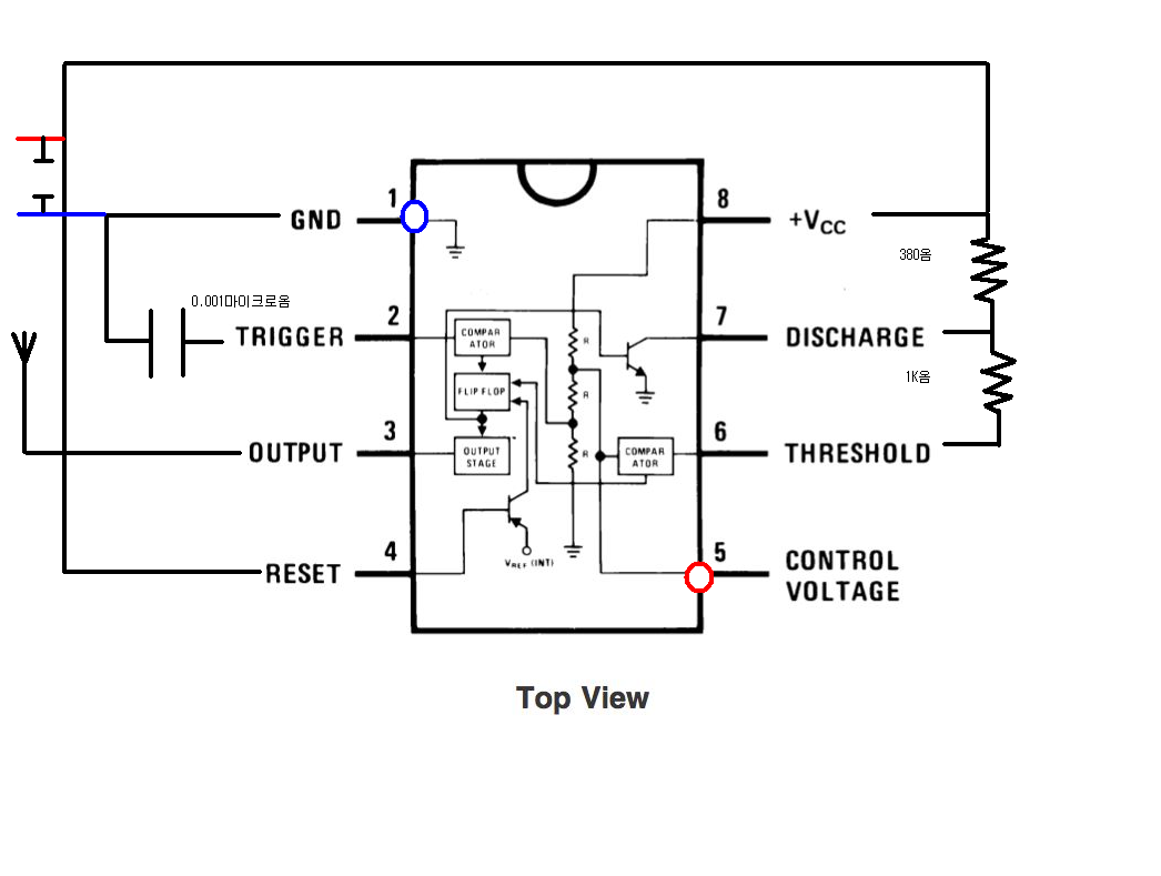
Circuit Diagram:

Click on the image to enlarge it.

simple digital Am transmitter circuit diagram.


AM TRANSMITTER.PNG

로그인 후 댓글쓰기가 가능합니다.

?

List of Articles
번호 분류 제목 날짜 조회 수
2344 Fatal error: Call to a member function get() on null in C:\AutoSet9\public_html\files\cache\template_compiled\4cfb1455260434e25c468dc186e72b58.compiled.php on line 101