
전압채배기(렉테나에 주로 이용)
1N34, 1N60, 1N277 Ge diode
전압을 X배로 높이기 위한 기술로 1913년에 그라이나허가 발명한 것이다.
"렉테나(Rectenna)"는 Rectifier(정류기)와 Antenna(안테나)를 합성한 말이다.
안테나의 맨 중앙부에 정류 다이오드를 접속하여 안테나에 마이크로파가 조사되면 전기적으로 공진하여 중앙부가 전류의 배로 된다.
참고 : http://www.ktechno.co.kr/mwapl/rectenna.html
검파회로 : http://www.rfdh.com/invite/ilab/j5.htm
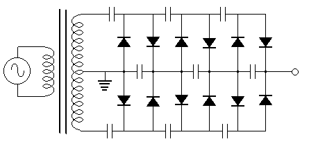
회로도
Villard circuit

Voltage multipliers


FULL-WAVE VOLTAGE MULTIPLIER
The following is circuit diagram for a three stage, full wave Cockcroft-Walton voltage multiplier. (Named after James Douglas Cockcroft and Ernest Thomas Sinton Walton). The diodes allow the capacitors to charge in parallel and discharge in series. More stages produce higher voltages and lower currents. The no-load output voltage is simply the number of stages multiplied by the peak input voltage. For each 10vAC (RMS) the output is 30 volts.
HALF-WAVE VOLTAGE MULTIPLIER
Most voltage multiplier circuits require very low current for their operation. They are used for their high voltage as a high voltage produces some amazing effects. For instance, if a high voltage (above about 5kV) is connected to a pin with a sharp point, a spray of electrons will fly off the point and produce an "electric wind." These electrons will accumulate on dust particles and drop them to the ground.
This is the principle of an electrostatic precipitator. If the voltage is increased further, ozone gas (O3) will be produced -that's why the voltage must be below about 15kV to avoid ozone being produced. This is the most corrosive gas known.
Cattle prods and insect zappers also use voltage multiplying circuits and these require a high voltage with very little current.
That's why a half-wave circuit can be used. It uses less components than full-wave but produces a lower current.
The principle of a voltage multiplying circuit is amazing. It charges capacitors in parallel and allows them to discharge in series.
Thus is something you cannot do with batteries - charge them in parallel and allow them to discharge in series to deliver a high voltage - so let's see how this is done.
Figure 1 shows the complete Voltage Multiplier circuit:

We will take the operation of the circuit in slow-motion and show how each capacitor charges. Once they are all charged, they get topped-up during each charging-cycle and the voltages are slightly different to the start-up cycles.
We will start with just C1. It is uncharged.
We start when the secondary winding has a peak of -100v at the top of the winding. This is to create a voltage on C1 as shown in fig2. If the secondary winding starts with +100v at the top of the winding, the capacitor will get charged in the wrong direction and this will be corrected during the next half-cycle, as the capacitor must be charged as shown in fig 2.
All the other components in the circuit have been removed as they are not involved during this instant. The voltage across D1 is almost zero and you can consider the positive of the capacitor to be connected to the + of the secondary winding. This means none of the rest of the circuit is receiving any energy.
 555 TIMER AM TRANSMITTER CIRCUIT(AM 송신 회로)