
FM 송신기 회로
Very compact microphone transmitter, 100 MHz.
Shoud fit on 1 x 1 cm piece of veroboard! ( ex mike. en batt. )
Tuning: basically done by adjusting the ferrite core. To adjust the range bend the coil.
The BC547 is used as an amplifying varicap. So it is actually drawn right!
The antenna is a piece of wire, use any length, but 1/8 wavelength may work better.
Range achieved in plain view can be 100 meter ++.

![]()

http://homemadecircuitsandschematics.blogspot.kr/2011/12/fm-wireless-microphone-circuit-design.html

http://www.buildcircuit.com/simple-steps-for-making-fm-transmitter/
Description:
After getting several comments from young electronic students , I am rewriting this article to make the FM transmitter making process more clear.
This tutorial is for making simplest FM transmitter using one transistor. You can make this project with less components and it is an easy and simple project for beginners.
Before you proceed, please see the schematic given below. In the schematic, you will see the components required for making an FM transmitter.The transmission range of this circuit is approximately 10-20 meters.
The schematic of FM transmitter is given below:
![]()
You need the following components for this experiment:
1. Q1- Transistor- 2N3904

2. Capacitors- 4.7pF, 20pF, 0.001uF, 22nF.
Note: 0.001uF has code 102 and 22nF has code 223.
3. Variable capacitor: VC1. It is also called trimmer capacitor. You can buy one from your local store. The capacitance range should be 0-100pF or 10-100pF. If you cannot get one, try to get a trimmer capacitor that has minimum capacitance of 20pF. You can also get such capacitor from your broken radio, but you may need assistance in getting that out from your radio.

4. Resistors- 4.7 kilo Ohm, 470 Ohm
5. Condensor/ Electret Microphone


On your electret microphone, you will see that on one of the pins, there is solder pad connected to the case of microphone. Remember that pin is always negative.
6. Inductor- 0.1uF.
6-7 turns using 26 SWG wire.
You need to scrap the ends of inductor, otherwise, the inductor won’t work. Check the video given below to know how to make an inductor.
![]()
Or you can also use another inductor.
 0.1uH
0.1uH
Learn to make an inductor for FM transmitter
7. Antenna: Use 15cm to 1 meter long wire for antenna. If you have a long antenna, the signal transmission will be better.
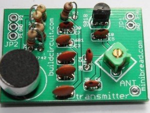
The following picture shows the components used for making FM transmitter. You can simply follow the steps shown below.
On the image shown below, you can notice that I have not used a trimmer/variable capacitor. I have used a fixed 20pF capacitor instead. So, if you don’t have a variable capacitor, you can use a fixed capacitor also.
![]()
![]()
Insert transistor, resistors and capacitors on breadboard. You can see the values of the components on the previous picture.
![]()
Then insert electret microphone.
NOTE: terminal touching the casing is -ve
![]()
![]()
Use 15cm long antenna. You can use a normal wire for antenna.
![]()
![]()
![]()
![]()
![]()
![]()
Then, with a non-conductive tool, adjust the capacitor for the clearest reception, rotate it till the receiver receives a sound from the microphone of transmitter. Use the following formula for determining the frequency.
Set your FM receiver for a clear, blank station.
Best of luck ![]()
BUILDCIRCUIT HAS RELEASED A NEW DIY FM TRANSMITTER KIT. PLEASE CLICK HERE TO KNOW MORE ABOUT THE KIT.
 FM 안테나 만들기(FM ANTENNA BUILD)
 FM 라디오 만들기