Skip to content
AVR
2014.12.15 13:01

2k fm

조회 수 5174 추천 수 0 댓글 0
?

단축키

Prev이전 문서

Next다음 문서

크게 작게 위로 아래로 댓글로 가기 인쇄
?

단축키

Prev이전 문서

Next다음 문서

크게 작게 위로 아래로 댓글로 가기 인쇄


출처 : http://www.circuitstoday.com/2-km-fm-transmitter

2 km FM transmitter


Description.
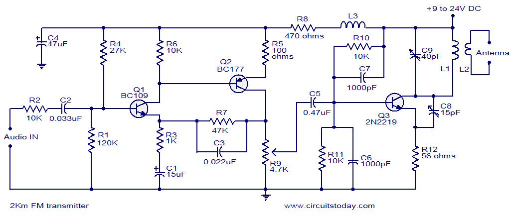
With a matching antenna, the FM transmitter circuit shown here can transmit signals up to a range of 2 kilo meters. The transistor Q1 and Q2 forms a classic high sensitive preamplifier stage. The audio signal to be transmitted is coupled to the base of Q1 through capacitor C2. R1, R3, R4, R6, R5 and R9 are the biasing resistors for the preamplifier stage comprising of Q1 and Q2. Transistor Q3 performs the collective job of oscillator, mixer and final power amplifier.C9 and L1 forms the tank circuit which is essential for creating oscillations. Inductor L2 couples the FM signal to the antenna.

Circuit diagram.

2km Fm transmitter
Notes.

  • Assemble the circuit on a good quality PCB.
  • The circuit can be powered from anything between 9 to 24V DC.
  • Inductor L3 can be a VK220J type RFC.
  • For L1 make 3 turns of 1mm enamelled copper wire on a 10mm diameter plastic former. On the same core make 2 turns of 1 mm enamelled copper wire close to L1 and that will be L2.
  • Frequency can be adjusted by varying C9.
  • R9 can be used to adjust the gain.
  • For optimum performance, value of C8 must be also adjusted.
  • Using a battery for powering the circuit will reduce noise.
로그인 후 댓글쓰기가 가능합니다.

?

  1. 25
    Mar 2014
    11:15

    1-200 transistor circuits(트랜지스터 회로 200가지)

    Category회로도전자부품 Views10359
    Read More
  2. 12
    Oct 2013
    14:19

    1.5V to 5V/12V DC/DC Converter with LT1073

    Category회로도전자부품 Views24694
    Read More
  3. 09
    Jan 2014
    13:54

    1.5V 단일 트랜지스터 FM 송신기 만들기

    Category회로도전자부품 Views9726
    Read More
  4. 14
    Jan 2014
    18:59

    1석 오디오 회로도

    Category회로도전자부품 Views7277
    Read More
  5. 25
    Nov 2015
    23:45

    2 TRANSISTOR CIRCUITS

    CategoryAVR Views4512
    Read More
  6. 25
    Nov 2015
    23:48

    2 트랜지스터 비안정 바이브레이터 회로(펄스)

    CategoryAVR Views5099
    Read More
  7. 07
    Jul 2015
    08:38

    2.4Ghz Bi-Quad Antenna

    Category회로도전자부품 Views1816
    Read More
  8. 02
    Jul 2015
    08:07

    2.4Ghz 안테나

    Category회로도전자부품 Views1232
    Read More
  9. 16
    Feb 2016
    02:10

    2.7V 500F 슈퍼캡 충전시키기

    Category회로도전자부품 Views1776
    Read More
  10. 15
    Dec 2014
    13:01

    2k fm

    CategoryAVR Views5174
    Read More
  11. 22
    Aug 2019
    15:05

    2n2222 Esaki Effect 트랜지스터 주파수 발생기

    Category회로도전자부품 Views6801
    Read More
  12. 07
    Feb 2014
    08:27

    2석 오디오(트랜지스터 오디오)

    Category회로도전자부품 Views9829
    Read More
  13. 31
    Aug 2013
    13:17

    555 PWM 회로 단계 동영상

    Category회로도전자부품 Views21465
    Read More
  14. 01
    Dec 2015
    08:36

    555 TIMER AM TRANSMITTER CIRCUIT(AM 송신 회로)

    Category회로도전자부품 Views3691
    Read More
  15. 20
    Sep 2014
    13:09

    555 TIMER AM TRANSMITTER CIRCUIT(AM 송신 회로)

    CategoryAVR Views23299
    Read More
  16. 21
    Sep 2013
    09:46

    555 timer Brigde control

    Category회로도전자부품 Views14462
    Read More
  17. 15
    Oct 2013
    00:06

    555 Timer Led 교차하여 깜빡이기

    Category회로도전자부품 Views18153
    Read More
  18. 03
    Aug 2012
    11:33

    555 타이머 회로 응용

    CategoryAVR Views8109
    Read More
  19. 02
    Nov 2017
    15:25

    555타이머(555 timer 60Hz clock circuit)

    Category회로도전자부품 Views5514
    Read More
  20. 29
    Oct 2013
    16:50

    555타이머의 Duty-Cycle을 55%이하로 사용시 회로도

    Category회로도전자부품 Views14606
    Read More
Board Pagination Prev 1 2 3 4 5 ... 13 Next
/ 13

http://urin79.com

우린친구블로그

sketchbook5, 스케치북5

sketchbook5, 스케치북5

나눔글꼴 설치 안내


이 PC에는 나눔글꼴이 설치되어 있지 않습니다.

이 사이트를 나눔글꼴로 보기 위해서는
나눔글꼴을 설치해야 합니다.

설치 취소